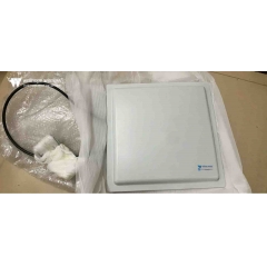

 Antena de roteador WiFi
Polarização da Antena: O Que É e Por Que Importa
Tempo estimado de leitura: 15 minutos
Todo engenheiro eletrônico sabe que as antenas transmitem e recebem sinais na forma de ondas eletromagnéticas (ondas de energia eletromagnética), cujas propriedades podem ser descritas pelas equações de Maxwell. Como muitos assuntos técnicos especializados, podemos interpretar essas equações, juntamente com as regras de propagação e as características das ondas eletromagnéticas, a partir de múltiplas dimensões — variando de descrições qualitativas relativamente simples a fórmulas matemáticas complexas e detalhadas.
A polarização é uma das inúmeras características da propagação da energia eletromagnética. Seus impactos e o grau em que precisa ser considerada variam amplamente entre diferentes cenários de aplicação e os respectivos projetos de antenas. Os princípios fundamentais da polarização se aplicam a toda radiação eletromagnética, incluindo sinais de radiofrequência (RF)/sem fio e energia de ondas luminosas, e a polarização tem amplo uso no campo da óptica. Este artigo aborda apenas a faixa de frequência de RF.
O Que É Polarização da Antena?
Para compreender a polarização, é necessário primeiro dominar os conceitos básicos das ondas eletromagnéticas. Uma onda eletromagnética consiste em um campo elétrico (campo E) e um campo magnético (campo H) que viajam na mesma direção. O campo elétrico e o campo magnético são perpendiculares entre si, e ambos são perpendiculares à direção de propagação da onda plana.
A polarização é definida como o plano de vibração do campo elétrico quando observado a partir da extremidade transmissora na direção de propagação da onda. Na polarização horizontal, o campo elétrico oscila de um lado para o outro dentro do plano horizontal; na polarização vertical, o campo elétrico vibra para cima e para baixo dentro do plano vertical (consulte a Figura 1).

Figura 1: Onda eletromagnética com componentes de campo elétrico e magnético mutuamente perpendiculares
As antenas transmissora e receptora formam um par de antenas, e o desempenho do transceptor atinge seu pico quando as duas compartilham planos de polarização idênticos. Fazendo uma alusão à frase icônica do filme de 1979 Alien— “No espaço, ninguém pode ouvir você gritar” — não há distinção inerente entre polarização horizontal e vertical no espaço sideral. Mesmo assim, as teorias de correspondência de polarização e alinhamento de antenas continuam válidas para maximizar a transmissão e recepção de energia do sinal.
Polarização Linear e Circular
As ondas eletromagnéticas apresentam vários modos de polarização:
- A polarização linear básica inclui duas formas de polarização ortogonais (perpendiculares) entre si (consulte a Figura 2). Teoricamente, uma antena receptora polarizada horizontalmente não pode capturar nenhum sinal emitido por uma antena transmissora polarizada verticalmente operando na mesma frequência, e vice-versa. Quanto mais próximas forem as orientações de polarização das duas antenas, mais forte será o sinal recebido; a eficiência de transferência de energia do sinal atinge o pico quando a polarização está perfeitamente compatível.

Figura 2: A polarização linear oferece duas formas de polarização mutuamente ortogonais
- A polarização inclinada é uma variante da polarização linear. Assim como a polarização horizontal e vertical padrão, essa definição se aplica apenas a cenários terrestres. A polarização inclinada forma um ângulo de ±45° em relação ao plano horizontal. Embora a polarização inclinada seja fundamentalmente linear, quando profissionais do setor se referem a “polarização linear”, geralmente querem dizer apenas antenas com polarização horizontal ou vertical.
- Os sinais emitidos ou recebidos por antenas com polarização inclinada podem ser captados por antenas puramente polarizadas horizontal ou verticalmente, embora com certa perda de sinal. Antenas com polarização inclinada são ideais para casos de uso em que o estado de polarização de uma ou ambas as antenas é desconhecido, ou quando a polarização muda durante a operação.
- A polarização circular (CP) é mais complexa que a polarização linear. Nesse modo de polarização, o vetor do campo elétrico gira continuamente à medida que o sinal se propaga. Quando observado para fora a partir da extremidade transmissora, o giro no sentido horário do vetor do campo elétrico é chamado de Polarização Circular Direita (RHCP); o giro no sentido anti-horário é chamado de Polarização Circular Esquerda (LHCP) (consulte a Figura 3).

Figura 3: O vetor do campo elétrico das ondas eletromagnéticas com polarização circular gira, dividido nos tipos direito e esquerdo
Sinais com polarização circular são formados pela sobreposição de duas ondas eletromagnéticas ortogonais com uma diferença de fase de 90°. Três critérios devem ser atendidos para gerar polarização circular: o campo elétrico deve conter dois componentes ortogonais; os dois componentes devem ter uma diferença de fase de 90°; e ambos os componentes devem ter a mesma amplitude. Antenas helicoidais oferecem uma solução simples para gerar ondas com polarização circular.
- A polarização elíptica (EP) é uma derivação da polarização circular. Assim como as ondas com polarização circular, as ondas com polarização elíptica são sintetizadas a partir de duas ondas com polarização linear. A polarização elíptica se forma quando duas ondas linearmente polarizadas mutuamente perpendiculares com amplitudes desiguais são sobrepostas.
O grau de incompatibilidade de polarização entre duas antenas é quantificado pelo Fator de Perda de Polarização (PLF), medido em decibéis (dB). Seu valor é determinado pelo ângulo de polarização entre as antenas transmissora e receptora. Teoricamente, o PLF é igual a 0 dB sob correspondência perfeita de polarização (perda zero); se as duas antenas forem totalmente polarizadas de forma ortogonal, o PLF se aproxima do infinito (atenuação completa do sinal).
Em aplicações do mundo real, porém, as antenas não conseguem alcançar polarização perfeitamente compatível ou totalmente ortogonal. Desalinhamento mecânico na instalação, erros de operação humana, distorção do canal, reflexões por múltiplos caminhos e outros fatores introduzem desvios angulares na direção de polarização do campo elétrico transmitido. Mesmo que duas antenas sejam projetadas para polarização ortogonal, vazamento de polarização cruzada de 10 a 30 dB ou mais ainda ocorre na prática. Em alguns cenários, esse sinal vazado é forte o suficiente para interferir na demodulação do sinal desejado.
Por outro lado, mesmo com polarização ideal e alinhamento preciso de duas antenas, fatores ambientais do mundo real podem elevar o PLF para 10 dB, 20 dB ou mais, degradando a recepção do sinal. Em termos simples, a polarização cruzada não intencional e os altos fatores de perda de polarização produzem dois efeitos adversos: introduzem sinais interferentes e atenuam a intensidade do sinal útil desejado.
Por Que as Características de Polarização Importam
A polarização segue uma regra bidirecional: quanto mais alinhados e consistentes forem os tipos de polarização de duas antenas, maior será a intensidade do sinal recebido. Pelo contrário, uma baixa correspondência de polarização dificulta que tanto receptores do sinal desejado quanto receptores de interferência capturem sinais utilizáveis suficientes. Na maioria dos cenários, o canal sem fio altera o estado de polarização do sinal transmitido, ou um ou ambos os transceptores não conseguem manter uma orientação fixa e estacionária da antena.
A escolha do modo de polarização geralmente é determinada pelo ambiente de instalação e pelas condições de propagação atmosférica. Por exemplo, antenas polarizadas horizontalmente oferecem melhor desempenho de sinal e polarização mais estável quando montadas próximas a tetos; em contraste, antenas polarizadas verticalmente instaladas contra paredes laterais apresentam comportamento de polarização mais próximo das especificações nominais de projeto.
Antenas dipolo comuns (dipolos padrão / dipolos dobrados) operam em polarização horizontal sob montagem convencional (consulte a Figura 4). Se necessário para se adequar a um modo específico de polarização, a antena pode ser girada 90° para mudar para polarização vertical (consulte a Figura 5).
SHAPE \* MERGEFORMAT
Figura 4: Antenas dipolo normalmente são montadas horizontalmente em mastros para polarização horizontal
SHAPE \* MERGEFORMAT
Figura 5: As antenas dipolo podem ser instaladas verticalmente em mastros para polarização vertical quando exigido pela aplicação
A polarização vertical é amplamente utilizada em rádios comunicadores portáteis, como os dispositivos transportados por equipes de resgate de emergência. Isso ocorre porque a maioria das antenas de rádio com polarização vertical apresenta padrões de radiação omnidirecionais — o que significa que os usuários não precisam reajustar o azimute da antena mesmo quando a orientação do dispositivo portátil muda constantemente.
A maioria dasantenasque operam na banda de Alta Frequência (HF) de 3–30 MHz adotam estruturas simples de antenas de fio longo estendidas horizontalmente entre suportes. Seu grande tamanho físico é determinado pelo comprimento de onda correspondente (10–100 metros), e essas antenas são inerentemente polarizadas horizontalmente.
Curiosamente, a banda foi denominada “Alta Frequência” décadas atrás, quando 30 MHz era considerada uma faixa de alta frequência. Embora o rótulo pareça desatualizado hoje, ele permanece como a designação oficial da banda definida pela União Internacional de Telecomunicações (UIT) e ainda é usado universalmente.
A banda de Ondas Médias (MW) abrange de 300 kHz a 3 MHz. A polarização selecionada pelas estações de radiodifusão nessa banda depende de a estação utilizar ondas terrestres para cobertura de sinal forte em curta distância ou ondas celestes ionosféricas para transmissão de longa distância. Em geral, antenas com polarização vertical oferecem propagação superior de ondas terrestres, enquanto antenas com polarização horizontal são mais adequadas para comunicações por ondas celestes.
As comunicações via satélite dependem fortemente da polarização circular. Os satélites alteram constantemente sua atitude em relação às estações terrestres e a outros satélites. A eficiência da transmissão do sinal atinge o pico quando as extremidades de transmissão e recepção utilizam antenas com polarização circular; combinar antenas com polarização linear com antenas com polarização circular funciona, mas introduz um fator de perda de polarização mensurável.
As características de polarização são igualmente críticas para os sistemas 5G. Certos arranjos de antenas 5G de Múltiplas Entradas e Múltiplas Saídas (MIMO) utilizam tecnologia de polarização para empregar os recursos de espectro com mais eficiência, aumentando as velocidades de transmissão. Isso é obtido combinando diferentes modos de polarização dos sinais com multiplexação espacial de antenas (diversidade espacial). Esses sistemas transmitem dois fluxos de dados independentes simultaneamente, com cada fluxo alimentado por antenas separadas de polarização mutuamente ortogonal, permitindo que o receptor demodule os dois fluxos separadamente. Embora fatores não ideais, incluindo trajetos de propagação, distorção de canal, reflexões e efeitos de múltiplos caminhos, introduzam uma pequena interferência de polarização cruzada, os receptores a mitigam internamente.
Conclusão
A polarização é uma característica vital, porém frequentemente negligenciada, das antenas. A polarização linear (incluindo as variantes horizontal e vertical), a polarização inclinada, a polarização circular e a polarização elíptica são adequadas para diferentes cenários de aplicação. A orientação relativa e o grau de correspondência das antenas nas extremidades de transmissão e recepção controlam diretamente o desempenho geral de todo o enlace de RF. Uma grande variedade de antenas padrão que abrangem todos os tipos de polarização e bandas de frequência de RF está disponível comercialmente para fornecer esquemas de polarização adaptados a todas as aplicações-alvo.